
Applicable Products
| Part number | Description |
| ZETA-GEP-LTE4 (EU) | Low Power LTE Cat 4 European Modem with GPIO and GNSS |
| ZETA-G-GPRS | Entry Level GPRS Modem with GNSS (GL) |
| ZETA-N2-GPRS | Entry Level GPRS Modem (GL) |
| ZETA-NEP-LTE4 (EU) | Low Power LTE Cat 4 European Modem with GPIO |
| ZETA-NEP-LTEM (GL) | Low Power Global LTE Cat M Modem with GPIO |
| ZETA-NLP-LTE1 (EU) | Ultra Low Power European LTE Cat 1 Modem |
| ZETA-NLP-LTEM (GL) | Ultra Low Power Global LTE Cat M Modem |
| ZETA-N-LTE (EU) | High Performance LTE Cat 4 Modem with GPIO |
| ZETA-NSP-LTE1 (EU) | Low Power European LTE Cat 1 Modem |
Objective
Once a Siretta ZETA modem is powered on, a combination of its 3 LEDs light up, showing different stages of modem connection to a network (default state).
Also, assuming the network connection is achieved, the modem can send a receive AT commands.
If any of the above fails to materialise, a troubleshooting procedure will help to investigate and solve basic issues.
Solution
This application note covers the following:
- No LED indication
- Modem keeps rebooting
- Failure to connect to a modem serial port
- No response from the modem when using AT commands
- No Carrier when dialling Voice/ data calls
Demonstration of Solution
LEDs Not Lit
- Check the modem has been connected to the correct power supply
- Check the power connector is inserted correctly
- Check the power has been switched on at the mains
- Check the LED functionality has been set with either AT#SLED or AT#GPIO AT commands
Modem Reboot
If your Siretta modem keeps rebooting, please check the following procedures:
- Check the SIM card has been inserted correctly
- Check the power supply is correctly specified or you are using an approved Siretta PSU.
No Serial Connection
If your Siretta modem has no serial connection, please check the following procedures:
- Check the serial cable has been inserted correctly
- Check the serial cable has the correct pin alignment (see below)
- Check the modem emulator program has the proper settings (Factory settings = 115200, 8, n, 1)
- Check there isn’t another program interfering with the communication program
- Check there isn’t a conflict with communication port access
RS232 Serial Port Interface
This connector provides serial RS232 communication between ZETA-xxP modem and the connected equipment. The modem can be configured via the RS232 connection using AT commands as specified in the AT command manual.
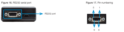
Table 15. Pins Usage
| Pin | Name | Usage | Status | Direction |
| 1 | DCD | Output from UART that indicates the carries is present | Connected | OUT |
| 2 | RXD | Output transmit line of UART | Connected | OUT |
| 3 | TXD | Input receive line of UART | Connected | IN |
| 4 | DTR | Input to UART and controls DTE ready condition |
Connected |
IN |
| 5 | GND | Ground |
Connected |
IN |
| 6 | DSR | Output from UART that indicates the module is ready |
Connected |
OUT |
| 7 | RTS | Request to Send – Input line of UART that controls hardware flow control |
Connected |
IN |
| 8 | CTS | Clear to Send – Output line of UART that controls hardware flow control |
Connected |
OUT |
| 9 | RI | Ring Indicator- Output line of UART that indicates the incoming call condition |
Connected |
OUT |
| Supported baudrates | |
| >> 2400 | >> 38400 |
| >> 4800 | >>57600 |
| >> 9600 | >>115200 |
| >> 19200 |
|
No Carrier Message
If your Siretta modem returns a ‘No Carrier’ message upon an attempted call (voice or data), please consider the following possible causes:
| If the modem returns… | Then ask? | Action |
| ‘No Carrier’ | Is the received signal strong enough? | Use ‘AT+CSQ’ to check RSSI.
Check signal strength indication. * |
| Is the antenna connected correctly? | Ensure antenna is firmly screwed into place. | |
| ‘No Carrier’
(When trying to issue voice communication) |
Is the semicolon ( ; ) entered immediately after the phone number in the AT command? | Ensure that the semicolon ( ; ) is entered after the phone number in the AT command. (e.g. ATD123456:) |
| ‘No Carrier’
(When trying to issue data communication) |
Is the SIM card configured for data/fax call? | Configure the SIM card for data/fax calls. (Ask your network provider if necessary) |
| Is the selected bearer type supported by the called partly? | Ensure the selected bearer type is supported by the call party. | |
| Is the selected bearer type support by the network? | Ensure the selected bearer type is supported by the network. | |
| If no success, try bearer select type by AT COMMAND: ‘AT+CBST=0,0,3’ |
| Value of RSSI | Interpretation |
| 0 to 12 | Insufficient or weak |
| 13 to 19 | Average |
| 20-31 | Good |
| 99 | No Signal |
Additional Reading
| Description | Author |
| ZETA Hardware user’s manual | Siretta |
| AT command manual | Telit |
| Quick Start Guide | Siretta |