
Antenna radiation plots – what do they mean?
An essential component of a wireless system is the Antenna selected to transmit and receive data. In order to optimise the system performance of a wireless installation it is highly recommended that designers look closely at their antenna selection.
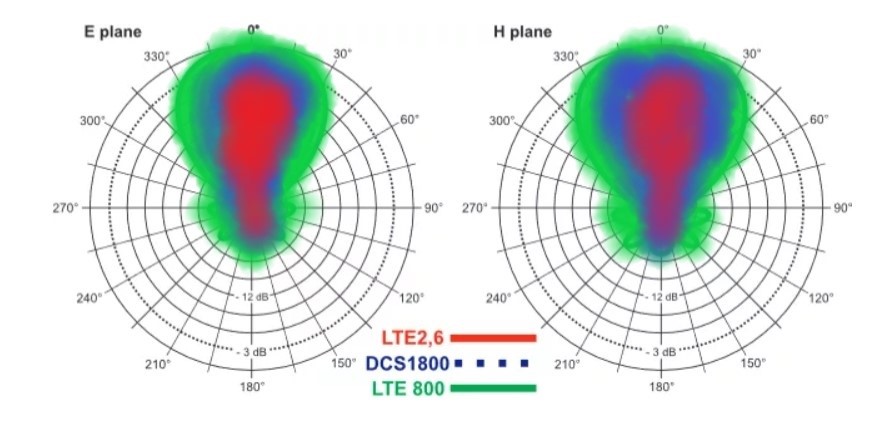
Antenna selection for any wireless or IoT system is a fundamental part of the overall system design. The antenna radiation plot or pattern gives clear indicators on how well the antenna dissipates the energy.
An antenna is a tuned electromagnetic device that is used in either single or multiple frequency bands. They can have various forms depending on: aesthetic requirements, environmental considerations and power capacity.
External sources and reflected signals can distort the radiation field measurements, so testing is made in an Anechoic chamber. An Anechoic Chamber absorbs radiated electromagnetic fields allowing the measurement of primary signals, without reflected energy, to produce gain and radiation plots.
Antenna Pattern Fields
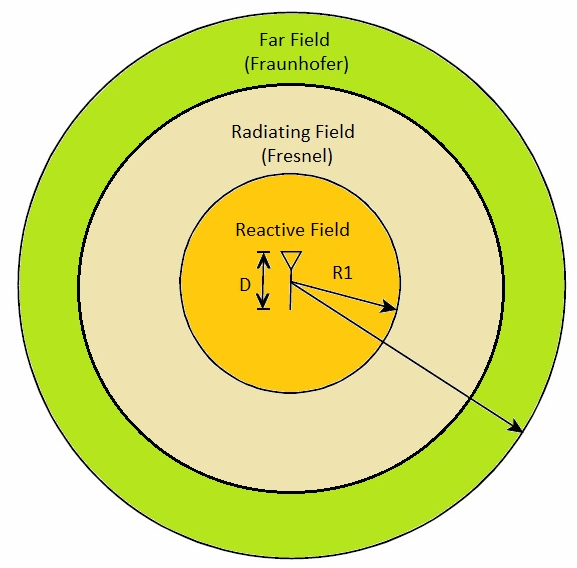
Antennas have different radiation pattern fields, depending on power, frequency and distance. Below is a list of definitions of these field regions.
Reactive Field Region – the region immediately surrounding the antenna where the reactive field energy – the standing wave is dominant.
Radiating-Field (Fresnel) Region – the region between the near-field and the far-field where the radiation fields are dominant, and the field is dependent on the distance.
Far-Field (Fraunhofer) Region – the region farthest away from the antenna, the field distribution is essentially independent propagating waves. The Size of these fields is determined by Antenna Size and the Wavelength of Transmission.
Far-Field (Fraunhofer) Region – the region farthest away from the antenna, the field distribution is essentially independent propagating waves.
The Size of these fields is determined by Antenna Size and the Wavelength of Transmission.
Antenna Energy Propagation
This shows the shape of energy propagation from the antenna. Basically, where transmitted data goes.
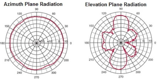
There are two main types of antennas:
Directional – An antenna with a more efficient radiation in one direction.

Omnidirectional – An antenna with a uniform radiation in plane. E or H (Power or Magnetic)
Antenna Patterns and their Parameters
A directional antenna radiation pattern is shown below. The patterns (Lobes) show the direction and power that is generated by the antenna. In an ideal ‘directional’ antenna design the radiation would be focused in one direction to give maximum gain.
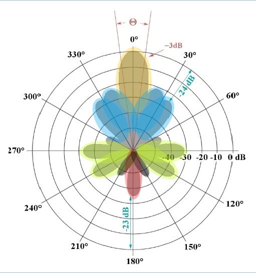
The lobes are defined as:
Radiation Lobe – a clear peak in the radiation intensity. (Main Lobe)
Minor Lobe – any radiation lobe other than the main lobe.
Side Lobe – a radiation lobe in any direction other than the direction(s) of intended radiation.
Back Lobe – the radiation lobe opposite to the main lobe.
Antenna Propagation Field Strengths
The circles in the above diagram represent the power levels measured in dB with 3dB being maximum gain shown on this chart. To best optimise the antenna the minor, side and back lobes are reduced, pushing the energy to the main lobe and improving the antenna performance. With omni-directional antennas, the lobes will be more uniform, but power will be reduced.
To select the best antenna for a system, design consideration should be given to the radiation diagrams supplied with the antenna, peak gain value, proximity to metallic objects and ground system, enclosure shape and material plus the actual site location that the system will be located on. The Siretta antenna selector tool can help to quickly identify potential antennas,
https://www.siretta.com/antenna-selector/
Siretta offers one of the widest ranges of antennas for a variety of applications covering GPRS, 3G, 4G/LTE, Sigfox, LoRA, Wireless LAN and GNSS technologies.