
Cellular Antenna installation and placement
The uses for antennas are endless and growing rapidly with this largely as a result of Internet of Things (IoT) device availability and diversity. The complexity when designing products using cellular continues to intensify with the number of frequencies the antenna needs to cover having increased significantly from the original technology of GSM/GPRS to the latest 4G/LTE and indeed forthcoming launch of 5G with the later requiring around 7 frequencies. The placement and orientation of an antenna within the device enclosure not only affects the performance of the antenna but has the potential to adversely influence the surrounding electronics and in worse case the mobile operator.
Original cell phones and modules used half wave antenna in the form of a simple wire or PCB track. Today the majority of most RF front ends now use MIMO (Many in, Many out) technology so that the antenna has multi functioning tuning to provide the wider range of frequencies.
The positioning and orientation of the antenna may seem to some to be inconsequential and in many instances thought about late in the design and indeed many designs will default to whatever is easily available. They may decide upon a standard 2G or 3G antenna and in numerous scenarios this approach may work however note that performance is likely to be compromised.
A tuned antenna placed in correct alignment will always maximise functionality, this is most apparent when operating in congested surroundings with a myriad of other cellular devices. This is particularly the case when operating at a greater distance from the signal source (remote sites) or in built up environments with metal and/or reinforced concrete structures (cities).
Polarisation
Cellular signals vary in their transmission style and how the wave will propagate through the air. Ideally a device antenna should be designed to be ‘circular polarised’ however most polar diagrams will have some gain in one direction (try rotating your cell phone when you have a weak signal). Optimum performance can be achieved by checking the antenna orientation to typical signal source, this is of greatest benefit in stationary remote applications which are connecting to the nearest fixed base station.
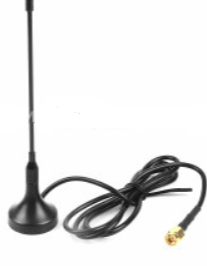
For some extreme remote applications, it may be beneficial to use a Yagi (multi element directional) antenna.
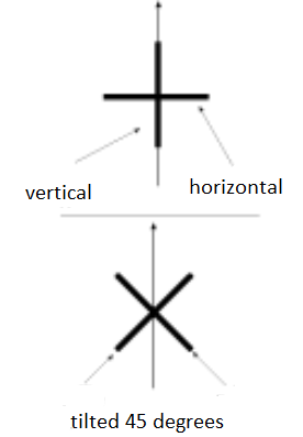
Cell towers will vary according to the type and age of construction, newer LTE towers have their antenna set up in an X shape so that they can transmit between Vertical and Horizontal polarisation. Aligning your antenna in the same way will maximises performance.
Device Enclosure
The module or device containing the cellular transceiver is typically designed to be placed inside an enclosure. For the best signal an external antenna would be ideal however aesthetics and user requirements around size and mobility normally remove this possibility, I don’t think any of us want to carry a cell phone with an external antenna as we did in the eighties.
Consideration needs to be given to the type of enclosure and the relative position of the antenna to the source of transmission. The cables or PCB tracks themselves connecting the output to the antenna will have a loss affect, the nearer to the source the better. If you are designing your own transceiver then you will have control of this, if you are using a standard module then you will be connecting via a coaxial type socket or soldered joint.
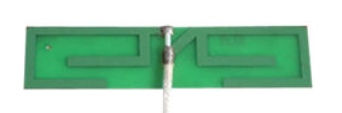
A typical PCB MIMO antenna a cellular module using 3G/4G and WiFi.
Alternatively, if the module is designed to be soldered to the PCB it may be possible to design the antenna within the tracks of the mounting PCB. In this case greater care of the antenna matching and a knowledge of the design parameters is required. This will also impact final testing for certification.
One of the most critical decisions once an antenna has been chosen is the location within the enclosure, one of the key elements to consider is the reduction of spurious emissions from the device. This will generally require screening around oscillators and high-speed processors as well as displays if end certification is to be accomplished.
Much press has been seen around the damage that radiation from mobile phones can cause the user. That said, to date, tests appear inconclusive although clearly consideration to minimising this is advantageous and can be achieved by building an enclosure using metal or plastic-coated metal. Enclosing an antenna in this way acts like a faraday cage blocking the electromagnetic fields. All designs require some compromise to achieve the greatest outcomes.
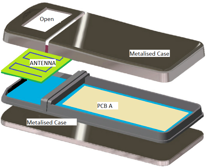
In the vast majority of designs there is a natural opening in the metallised case on the left for the display, this can offer a good location for the antenna, alternatively the antenna could be placed on the rear surface providing the metallization is removed.
Conclusion
Modern modules and mobile phones use more complicated MIMO antenna and these need to be optimised for the many frequency bands now utilised. Producing and locating the antenna to give the best match in both mobile or fixed applications requires careful alignment. In addition, the design of the enclosure to maximise radiation from the antenna whilst minimising the spurious unwanted signals from various sources makes the design and placement more complex.
