
Quite a lot of attention is paid to obtaining an antenna with high gain but does that always mean the strongest signal is delivered to the device? Below we explore areas of signal loss which can be minimised by best practices.
The coax cable type and length of cable used will be one of the most significant factors that reduces the available signal, both received and transmitted. In general, cable lengths should be kept to a minimum and where lengths above 5m are required, a low loss type should be used.
The operating frequency of the system will also come into play and the lower the frequency the less loss there will be. Lower frequency signals also travel better in the air and through buildings giving better overall transmission performance.
Cable Attenuation
Attenuation is the term given to the loss of signal along a length of cable. When a signal is attenuated it is lessened, much like water pressure in a pipe, it starts out strong but over distance the pressure weakens. With an RF (Radio Frequency) signal the amount of attenuation is also linked to the frequency of the waveform as much as the resistance and other factors in the cable, which we explore later.
Fig 1.0 illustrates the spread of performance for some of the common cables (attenuation shown in dB per 100m).
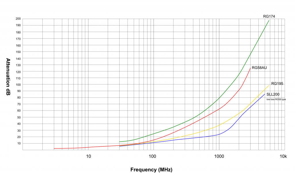
What’s a dB? This is short for decibel and is a way to logarithmically express a ratio.
It is common to use this expression to describe the loss or gain of power.
This information is interesting but what does that really mean when we typically only have short cable feeds to the antennas of sub 20m. The next graph explores the difference between a standard RG58 cable and a low loss type like the SLL200 used in our cable assemblies.
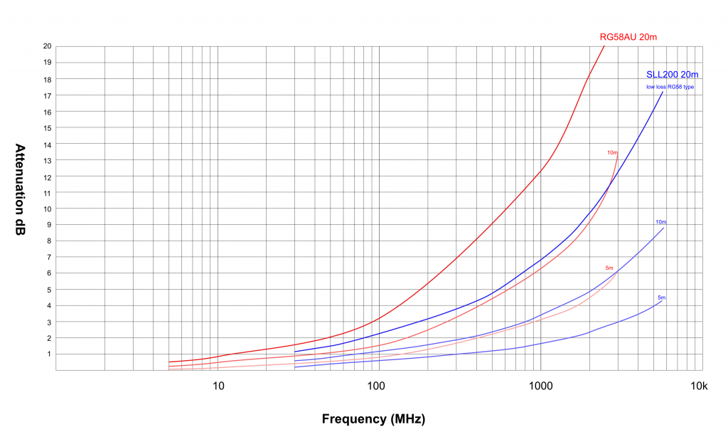
Fig 1.1 The same cable performance but now for 5m 10m and 20m cable lengths. It can be seen how a short length of cable can reduce the signal from the antenna or device, especially at higher frequencies.
The cable has a resistance to the signal which reduces the voltage (a combination of: the signal travelling the length of the cable, coupling loss though magnetic fields with the shield, return loss from imperfections in the cable, tight bends and adapters joining lengths of cable). A hefty list of issues, all with small effects but all which add up to create a loss, worthy of consideration. Some of which cannot be mitigated against and others which are affected by installation practices or purchase choices.
Installing a larger diameter cable could be the first ‘go to’ answer but cost will also be a factor. A higher quality cable of the same type will generally be a better compromise. Quality manufacturing will prevent cable imperfections of the core where surface damage can result in signals returning back down the cable (return loss).
Copper Cable Draw down Process
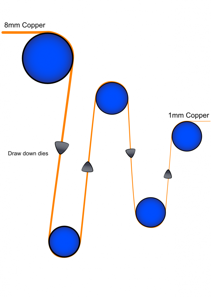 |
At the frequencies we are concerned with: starting from the lower megahertz ISM bands and cellular bands from 700MHz upwards, all signals travel on the surface of the centre conductor. With that in mind, any damage to the centre core can cause transmission issues. For single events this is unlikely to be troublesome but indentation can be caused by the machinery making the cable. A damaged pulley wheel used in the initial copper draw down from a larger diameter to the correct size, could cause an indent at regular pitches which reflect part of the signal.
Possible core damage through a draw down |
Core imperfections
 |
Imperfections on the surface of the central conductor can cause small parts of the signal to be reflected. A damaged pulley wheel in the wire draw down process could indent the wire at regular intervals causing a higher return loss than anticipated from the specification. |
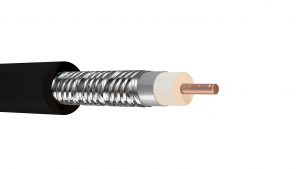
Coupling to the shield – foil or braid
|
Coupling is a mechanism by which an electric current in a cable produces an electromagnetic field that cuts across another conductor. In this case, the conductor is the cable shield which returns the current flow in the opposite direction. The energy lost in the coupling is part of the signal attenuation. Shown in the illustration is a cable with a 50-60% braid coverage. Whilst being a cheaper cable it is also less effective at shielding the core to outside interference. The size of the hole in the braid will let some frequencies pass through to the core. In addition, transient power spikes from mains cables laid parallel and next to the coax cable can cause signal distortion. |
 |
Whilst comms between devices may stay running, errors and retries for transmissions will use cellular bandwidth and could cost more depending on SIM contracts. With IoT devices passing small amounts of data back to server applications the extended transmissions will also affect modem battery life.
A device with a battery life expectancy of 5 years could be significantly reduced by staying powered up for longer to get transmissions completed each time it is scheduled to send data.
Impedance Mismatch – connectors / adaptors / cables
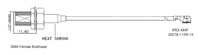
There are many RF connectors on the market and each will have its benefit, whether it be easy to connect/ disconnect or performance related. Joining 2 cable sections together will never be perfect and losses will occur. A lot of the time it might seem like there is only one cable linking to an antenna but, in reality there could be a small attachment cable inside the device. These cables typically have a PCB micro connector linking to a case mounted SMA connector with a very thin 1.13mm cable.
The more connections there are between the antenna and receiver electronic circuit, the more the signal is disturbed, distorted and reduced in strength.
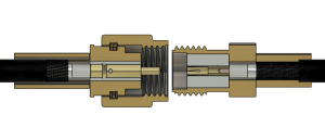
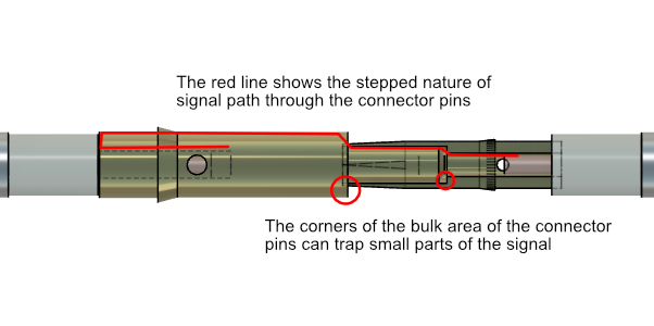
An SMA connector is illustrated below and the path from cable to cable is clearly not a smooth continuous path of the same size. Given that the frequencies we are concerned with travel in the ‘skin’ or on the surface we can see the transitions on the surface of the pin and socket will disrupt the signal in some form. A small part of high frequency signals will get reflected back down the cable or trapped in larger parts of the connector pins.
  |
|
Another feature of good connector design is ‘contact wipe’. Microscopic particles of dust and dirt can accumulate on the surface of unmated connections and can reduce the effective contact area for galvanic signal transmission. The female pin of the SMA connector has a scrape action that wipes the surface clean as the male pin is inserted. The same action also removes an oxidised surface to make a cleaner contact. Part of the signal passing through the connector will be through capacitive coupling and part through galvanic action (contact between the metal surfaces).
One or two cycles of connecting and disconnecting should clean the surface to provide the best signal through the connector.
Inside the body of the SMA Male nut is a small washer, shown in red, which will protect against moisture and dust ingress. The nut should be torque tightened (8-10in-lbs) to ensure a good seal and to prevent vibrations from loosening the nut.
Key Take-aways:
1. Avoid long cable runs where possible but use low loss types in lengths above 5m
The use of a quality, low loss cable means that you can keep as much of the signal collected by the antenna as possible. It also reduces the size of antenna required in an installation avoiding unsightly installations and targets for mindless vandalism.
2. Avoid intermediate connections and adaptors where possible
The use of multiple pieces of cable joined together with adaptors affects the signal quality and overall reliability of the system. Use them only as a temporary solution to trial installations or to adapt one connector type to another BUT, replace them with a single cable with the correct connectors on as soon as you can.
3. Be careful during cable installation and provide smooth bend transitions
If a quality cable is used, the affect of poor installation is lessened. As a rule of thumb, keep coaxial cables away from mains power cables by 100mm for 240V and 300mm for 415V. Avoid over manipulating the cable during installation and keep bends long and smooth. Manipulating low quality cable can breakdown the foil shield and open up the braid weave. Forcing the cable into tight bends and kinks can cause return loss.
4. When installing outdoors pay attention to connection points
Check the nut torque specifications to ensure the seal is maintained. Better still, protect any connection point by installing them in a weather proof enclosure. Also ensure the antenna is intended for use outdoors but don’t over specify ratings or a higher price may be paid. No need for 1m underwater protection (IP67) if just rainfall will be experienced. Antennas don’t typically work underwater anyway.