
Selecting an appropriate antenna can really make a design but get it wrong and communication will be less than ideal. This article concentrates on the main parameters to be aware of during the selection process. Consideration is given to the form factors covering both internal and external devices as well as the key electrical characteristics of gain, frequency response, impedance, directivity and polarization.
The end application should remain a primary driver in the evaluation process. Siretta’s Antenna selection tool is always available to help guide you to the right solution.
A principal constituent in selection is whether the end product is designed to be fixed or mobile. You may be fortunate if the device is in a strong signal area with a fixed application, however if you are in a weak area with a mobile device on the edge of a cell or consistently subject to poor weather conditions then the evaluation process is imperative and product selection critical to the success of your end product.
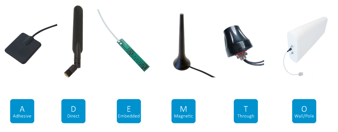
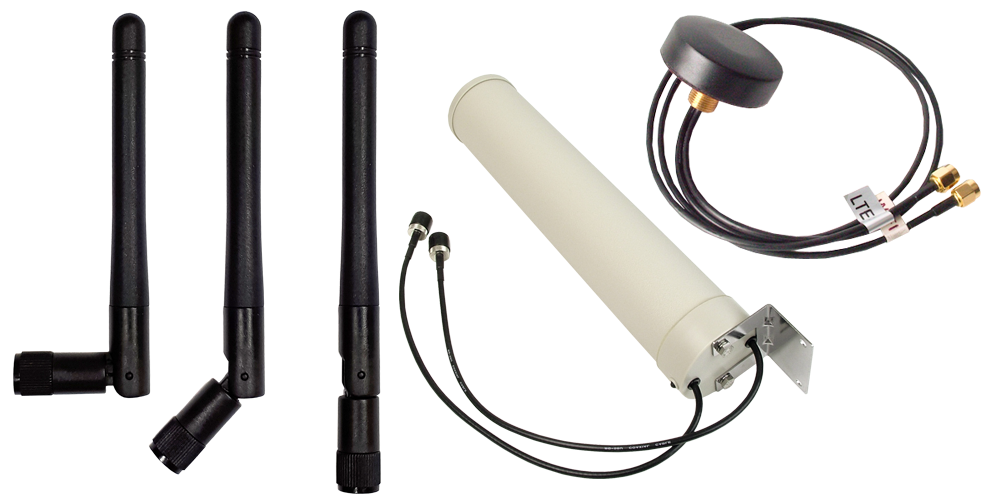
The form factor (physical form) of the antenna will to some degree be determined by the application and product design, Siretta offers a full range covering through hole, magnetic, adhesive, direct, embedded, wall and pole mount options.
For many mobile devices the ‘smaller the better’ approach is often primary, thereby steering the antenna selection towards embedded solutions, however, fixed equipment gives the opportunity to select from a wider antenna range where size and orientation are less critical.
Even with the wider selection opportunities offered by fixed locations there are additional considerations. Remote fixed locations with direct access to open space, for example: remote water pumping stations or storage depots will be best served by Yagi antenna designs with direct line of site to a providers antenna tower.
Directional antennas aligned with the nearest cell tower improve signal strength through the use of multiple elements in the antenna construction narrowing the beam to provide gain in one direction.
Other fixed locations, within cities and urban areas, are more likely to benefit from higher gain omnidirectional antenna designs which can interact with multiple cell masts on buildings.
The next selection criteria concentrate around the frequency bands required, historically this was less complex as older cellular equipment had fewer frequency bands. With the advent of 4G (LTE) and 5G (LTE) it has brought about an explosion in the requirements for multiband and MIMO (Multiple Input, Multiple Output) antennas for one device. More antennas improve the signal by collecting energy from multiple wave paths. For 2G and 3G applications, global compatibility exists but with 4G/5G LTE more complexity has been introduced; data rates are higher and the cell size is reduced bringing the need for more frequency bands. There are now around 70 frequency bands.
The decision on frequency/band is also be affected by the geographic location and available carriers in that region. For example, Vodafone will have different bands and frequencies to Verizon, Sprint or China Telecom. In deciding your choice of antenna it is important to understand even the widest band antenna is unlikely to be able to cover all 70 frequency bands and if they do, performance will fluctuate across them.
Having selected the equipment and carrier, antenna matching is the next consideration in the design. A perfectly matched antenna can bring improved performance by reducing mismatched impedance thereby reducing losses in standing waves (standing wave ratio SWR).
The antenna is a complex circuit of capacitance, inductance and resistance which becomes a tuned circuit when attached to a transmitter or receiver this is the impedance of the antenna and is typically honed to 50 Ohm’s.
The output of the cellular device will have a manufacturer recommended impedance, which is important to match with selection of the antenna. However, if you are designing an embedded antenna with a pcb modem then a matching circuit, with a combination of capacitance, resistance and inductance will be required.
The desired frequency or band will have different criteria to achieve a perfect match so it is therefore a balance which achieves a compromise and an overall level of performance acceptable to the needs of the device receiver.
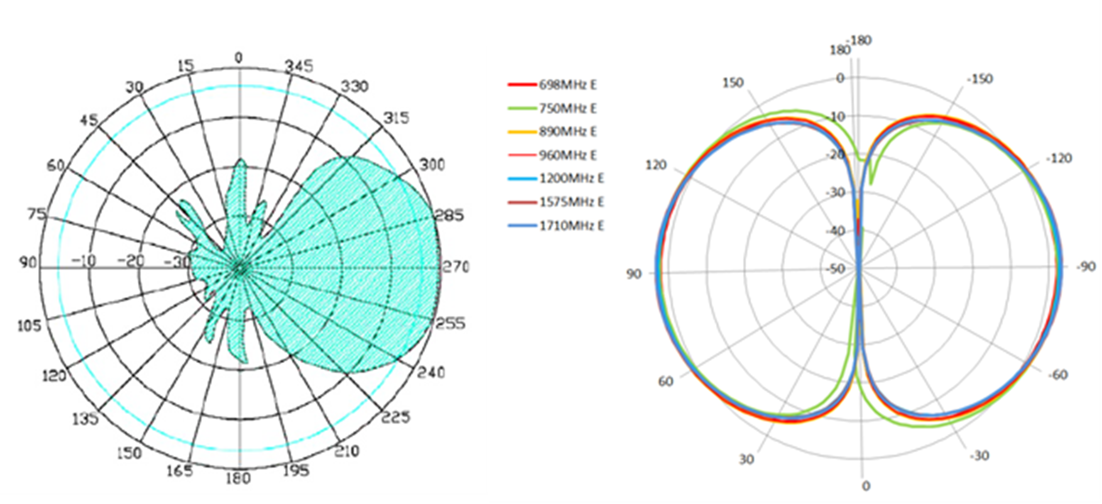
Antennas can transmit the signal in different ways and orientations, and this can be either linear or circular. Linear signals can be propagated in either the horizontal or vertical plane which is called polarisation. Circular wave propagation can either be RH, Right Hand or LH Left Hand meaning clockwise or anticlockwise. The orientation and propagation of the wave from the antenna should be carefully checked. If correct it will maximise the available performance of antenna, however, incorrectly oriented it can reduce the signal level drastically by up to 20dB.
In conclusion, choosing the correct antenna will improve the reliability and performance of any radio equipment. In industrial modems the choice and style is mainly determined by the manufacturer and specified in the datasheet. In remote locations with weak signals, directional antennas will certainly prove beneficial. On embedded equipment the choice is much more involved, particularly with PCB style antennas.
Siretta offers a vast array of antennas from embedded PCB designs through to high gain directional pole mounted Yagi types. Siretta are a leading manufacturer and developer of IoT products, IoT software and IoT solutions with a specialty in providing these for Industrial markets and business to business applications. Siretta have extensive knowledge and experience within IoT with a focus on cellular technologies in support of 2G (GPRS), 3G (UMTS), 4G (LTE Cat 1), 4G (LTE Cat 4), LTE Cat NB-IoT and LTE Category M. Products include cellular modems & terminals, routers, cellular network analysers, RF antennas, RF adapters and low loss RF cables.
