
Applicable Product
This application note is applicable to any Flexible Printed Circuit (FPC) antenna from Siretta’s range of antennas.
At the time of publication, the following FPC antennas are available:
| Part number | Description |
| ECHO44/0.1M/UFL/36 | 5G C-Band and Wi-Fi 7 Flexible Printed Circuit Antenna |
| ECHO44/0.1M/MHF4/36 | 5G C-Band and Wi-Fi 7 Flexible Printed Circuit Antenna |
| ECHO47/0.1M/UFL/36 | 5G/4G Flexible Printed Circuit Wideband Antenna 600-6000 MHz |
| ECHO47/0.1M/MHF4/36 | 5G/4G Flexible Printed Circuit Wideband Antenna 600-6000 MHz
|
Objective
FPC antennas bring designers the benefits of being able to be bent to fit into available space within an enclosure, as well as having an extremely low profile and little weight. However, to be able to realise the data sheet specification of these antennas, it is important to instal them correctly.
The objective of this application note is to explain how to correctly instal an FPC antenna in an application without damaging it, while obtaining the best radio performance.
Solution
Background
An FPC antenna is made from a copper foil (forming the active radio part of the antenna) glued to a sheet of polyimide film. This results in a bendable antenna that is less than 0.15 mm thick. The polyimide film gives the antenna strength, preventing the copper foil from being damaged, while still retaining flexibility. Polyimide film is also a good electrical insulator, chemically stable, and does not attenuate radio signals.
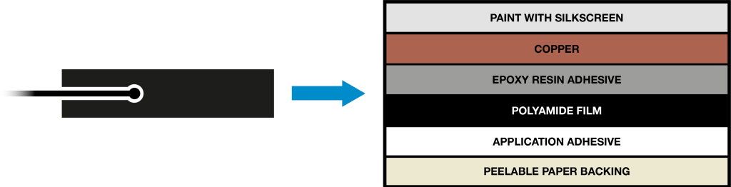
The FPC antenna ships with adhesive transfer tape pre-applied to the antenna. The tape uses 3M low surface energy acrylic adhesive 300LSE which may be used to attach the antenna to many hard to bond materials such as polypropylene, polycarbonate and ABS plastic.
The antennas may be available with U.FL or MHF4 connectors. This is an ordering option. MHF4 is the latest RF connector and is slightly smaller than the U.FL connector. Generally, MHF4 is used for 5G applications and U.FL with older radio standards such as WiFi, GSM, UMTS and LTE.
Antenna Placement
FPC antennas do not require an external ground plane to work, and so are ground plane independent.
However, being ground plane independent does not mean that it is wise to place an FPC antenna close to a ground plane or other large metal surface. The ground plane will block the radio signal to/from the antenna. Most printed Circuit Boards (PCBs) contain ground planes, so in general it is wise to consider this. Place the antenna so that the PCB and any other metal objects in the path that the radio signals need to take to establish a radio link is minimised.
PCBs can also contain processors and high-speed clock lines. Again, it is advisable to keep the antenna separated from these potential sources of interference.
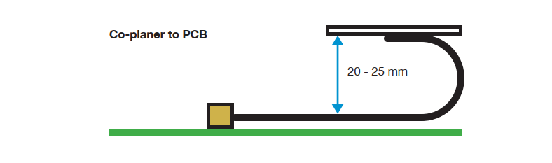
So, what is the recommended separation between FPC antenna and ground planes/large metal surfaces? There is no right answer to this question as it depends on many factors. However, Siretta suggests that 20 – 25 mm should be the minimum distance when the FPC antenna is co-planer to the PCB.
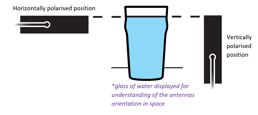
Another consideration for antenna placement is the polarisation of the antenna. Most modern radio data systems such as cellular, WiFi and IEEE802.15.4 expect to use vertical polarisation. Polarisation of the antennas at each end of the radio link ideally should be matched, and so the expectation is that the FPC antenna should be mounted in the vertically polarised position. However, in practice there are likely to be many reflection paths between both ends of the radio link. This will provide cross-polarization and make the antenna orientation somewhat irrelevant unless there is a clear line of sight between both ends of the radio link that has few reflection paths (such as a radio link across a field). Please read the Siretta Antennas 101 eBook to understand more about polarisation. To be vertically polarized, the antenna Z plane should point up to the sky.
Mounting surface
The main consideration for the mounting surface is that it is transparent to radio waves and will not reflect or absorb them. This generally means avoiding metals and other materials that are electrically conductive or magnetically permeable (since radio waves are electro-magnetic waves). Plastics, of any type, are generally good choices unless they are glass filled or coated with metallic paint.
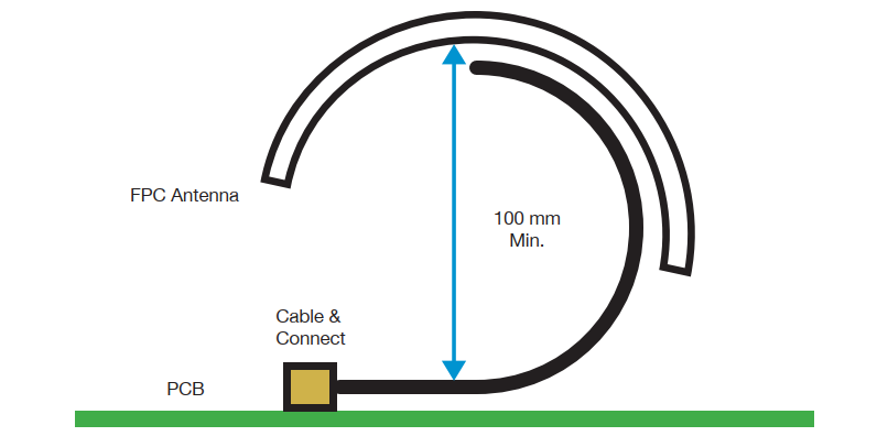
The mounting surface can be flat but doesn’t have to be. One of the benefits of a FPC antenna is that it can be bent and mounted on curved surfaces. It is recommended that the bend radius be not less than 100 mm as otherwise excessive strain will be placed on the epoxy adhesive used in the construction of the antenna. Sirettas FPC antennas are characterised and tested on both flat and curved surfaces to ensure that the antenna meets expectations no mater how it is mounted.
Cable Management
The integrated 1.13 mm coaxial cable is part of the antenna and needs to be routed to the mating connector in a way that minimises noise interference. Do this by trying to keep it over grounded areas and avoiding high rf emission parts of the product such as processors, high speed clock lines and display drivers. Any bends in the cable should have a bend radius (90 degree bend) of no less than 9.1 mm otherwise the VSWR/Return Loss specification could be compromised.
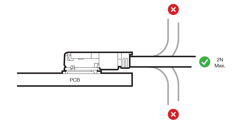
At the mating connector, the cable should run flat along the PCB so that there is no leverage stress applied to the connector which could damage the connector and break the connection. If necessary, it is suggested that some hot melt glue be applied to the cable to attach it to the PCB to provide stress relief.
I-PEX MHF I and MHF 4 connectors
The I-PEX MHF I connector is also known as (and will mate with) Hirose U.FL, Amphenol AMC and Sunridge MCB connectors. The I-PEX MHF 4 connector is also known as (and will mate with) Murata HSC connectors.
These connectors may be attached either by hand, or by using an attachment tool designed for the purpose.
I-PEX attachment tool part numbers are:
I-PEX 90435-001 (MHF4)
I-PEX 90224-0001 MHF I
Please refer to documentation from I-PEX for the correct way to use these tools. If attaching by hand, please follow these instructions:
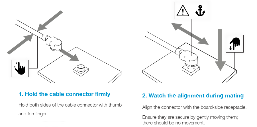
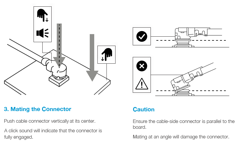
Instructions for mounting I-PEX MHF I and MHF 4 connectors (by hand)
Using the adhesive tape to bond the antenna to a surface
The ideal temperature at which to bond the FPC antenna to a surface is 20°C to 38°C. At this temperature the adhesive will have a very high initial adhesion. The bond strength will increase with time and temperature artier the antenna has been applied to a surface.
For the best bond strength, the surface to which the antenna is being attached should be dry, clean and well unified. If cleaning is required, use a cleaning solvent such as isopropyl alcohol.
Application below 10°C is not recommended since the adhesive becomes too firm to adhere readily. However, once properly applied, the adhesive will work satisfactorily at low temperatures.
Environmental
Each FPC antenna data sheet includes the operational temperature range for the antenna. These need to be respected as otherwise the bond to the surface on which the antenna is mounted could fail, especially if it is mounted on a curved surface.
Contact with solvents which could degrade the bonds of the adhesives used both in the antenna manufacture and to attach the antennas should be avoided.
Demonstration of Solution

Disclaimers and Waivers
Safety Disclaimer: The installation of this antenna should be carried out in accordance with local safety regulations. The manufacturer is not responsible for damages or injuries resulting from improper installation or use.
Professional Recommendation: For optimal performance and safety, we recommend installation by a qualified professional. Improper installation may void the warranty and could lead to poor performance or safety hazards.
Compliance Statement: Ensure compliance with all local building codes and electrical safety standards. The manufacturer is not liable for any violations of such regulations.
General/Ongoing Maintenance: Regular maintenance checks are essential for sustained performance and safety. Failure to conduct these checks could result in unexpected performance issues and safety risks.
Installation Confirmation: Upon installation, it is the responsibility of the installer to ensure that the antenna is securely mounted and functioning as intended. The manufacturer is not liable for issues arising from installation errors or oversights.
Additional Reading
| Description | Author |
| Siretta Antennas 101 eBook | Siretta |
| MHF I connectors | I-PEX |
| MHF 4 connectors | I-PEX |
| ECHO 44 datasheet | Siretta |
| ECHO 47 datasheet | Siretta |