
Applicable Products
| Part number | Description |
| ZETA-GEP-LTE4 (EU) | Low Power LTE Cat 4 European Modem with GPIO and GNSS |
| ZETA-G-GPRS | Entry Level GPRS Modem with GNSS (GL) |
Objective
Testing performance of antennas prior to selection can be a beneficial exercise in saving time and money. The antenna can be tested in a real environment at different locations to test its suitability.
This can be achieved by employing a Siretta GNSS enabled cellular modem.
Demonstration of Solution
Requirements
- Siretta GNSS Modem such as ZETA-GEP-LTE4 (EU)
- PC with Tera Term Version 4.96 (Tera Term can be downloaded from the following link – Tera Term Link).
- PC with VisualGPSView (VisualGPSView is a free software application. It can be downloaded here Visual GPS Linkfor Windows 7 to Windows 10)
- RS232 to USB cable (This cable is available with the ZETA starter kit – Siretta Part Number: 60793).
- GPS antenna to be tested (For this Guide the Mike 3A with SMA Male connector was used – Mike 3A)
Procedure for testing GPS antenna performance
1. Connect ZETA-GEP-LTE4 (EU) (or any other Siretta GNSS) Modem to the PC using USB to RS232 cable supplied.
2. Power ON the Modem (refer to Basic Modem Functions and Enhanced Modem Functions application notes).
3. Open Tera Term window on the PC connected to the modem.
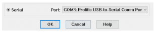
4. Select Serial and you should see “Prolific-to-Serial com port” as shown below.
5. Open setup tab on Tera Term then select serial port, you will be presented with the following screenshot.
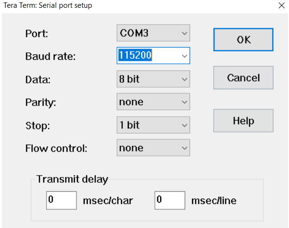
6. Enter the following parameters (see above):
• Bits per second: 115200
• Data bits: 8
• Parity: None
• Stop bits: 1
• Flow control: non
7. Click OK. The Tera Term window will open allowing you to send AT commands to the modem.
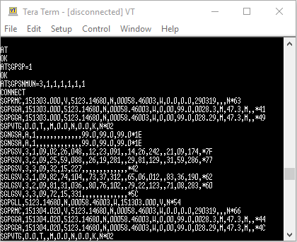
8. Send the AT commands shown below:
a) AT (You will receive OK) – Checks Modem is responding to AT commands
b) AT$GPSP=1 (You will receive OK) – Turns on GNSS engine inside the modem
c) AT$GPSNMUN=3,1,1,1,1,1,1 (receive CONNECT) – Turns on NMEA data stream
The NMEA GPS data strings will appear as shown below.
9. Click file tab on the Tera Term window, select disconnect as seen below.
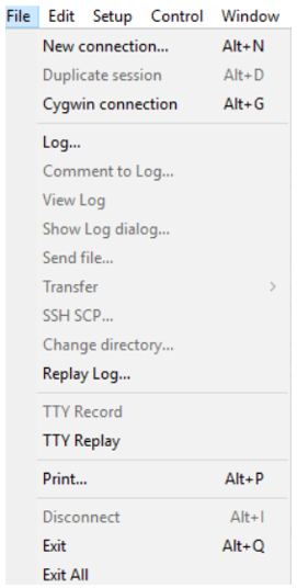
10. Click file tab on the Tera Term window, select disconnect as seen below.
11. Once disconnected from Tera Term, open Visual GPS View on the same PC. You will find Menu Bar below.
| Menu Bar |
| File Edit View Tools Help |
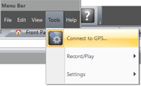
12. Navigate to Tools, then select “Connect to GPS “option as shown below.
13. Pop up screen below will appear. Select com port 3 and enter the baud rate of 115200 then click OK.
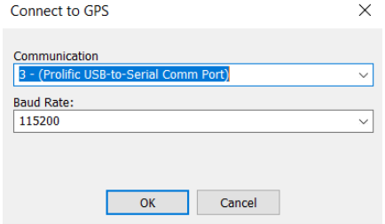
The setting is now complete.
14. Connect the GPS antenna to be tested to the modem GPS connector, then click “Front Panel Status” from the VisualGPSView where you will be presented with results shown below
NOTE:
• GPS reception is affected by line of sight to the satellite.
• You should adjust the GPS antenna position to find best reception which will ideally be outside or close to a window.
• If comparing antennas, you should therefore always place the antennas under test in exactly the same location every time to ensure a fair comparison.
Figure 1 shows the GPS results with the GPS antenna connected.
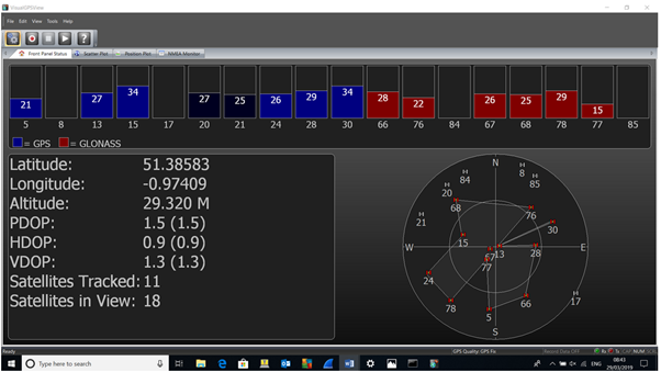
Figure 1
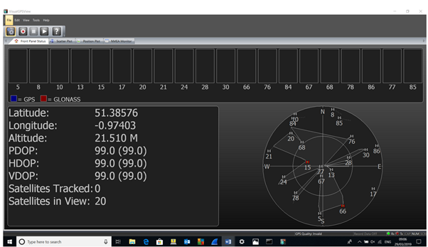
Disconnect the GPS antenna from the modem GPS connector then click “Front Panel Status” from the VisualGPSView where you will be presented with below results which show poor performance.
Figure 2 shows the results with no GPS antenna connected.
15. Results from VisualGPSview can be analysed by observing the GPS Quality entry as displayed below the satellite locations chart:
• GPS Quality: Invalid means that Poor GPS antenna performance or GPS antenna is not connected to the Modem or GPS antenna is faulty (see figure 2)
• GPS Quality: GPS Fix means that Good GPS antenna Performance (GPS fix is the locational information that the GPS system provides for a specific point see figure 1)
NOTE:
• DOP (Dilution of Precision) (range 0.9 to 99 is an indicator of how accurate the GPS signal results are. (A low DOP value means a good GPS signal result (see Figure 1), whereas a high value of DOP means a bad GPS result – see figure 2)
• If two antennas give the good GPS results, the antenna with a lower DOP value is more accurate than an antenna with a higher DOP value.
Definition of terms used in VisualGPSview.
GPS – Global Positioning System.
GLONASS – GLObal NAvigation Satellite System.
LATITUDE – is a geographic coordinate that specifies the north to south position of a point on the Earth’s surface.
LONGITUDE – is a geographic coordinate that specifies the east to west position of a point on the Earth’s surface
DOP- Dilution of Precision or GDOP Geometric Dilution of Precision is a term used in GPS and geomatics engineering to specify the error propagation as a mathematical effect of navigation satellite topology on positional measurement precision.
PDOP – Position (3D) Dilution of Precision
HDOP – Horizontal Dilution of Precision.
VDOP – Vertical Dilution of Precision
Satellites Tracked – Satellites Tracked by receiver
Satellites in View – Total satellite in View
GPS Quality – GPS Fix (Good antenna performance) / Invalid (Poor antenna performance/ antenna not connected / Faulty antenna).
Scatter Plot – The scatter plot shows individual position samples referenced to several type of reference types, next sample, average or user defined
Signal Quality/SNR Window – Monitors satellite signal to noise ratios and shows them graphically on the screen. The signal quality window will grow or shrink to accommodate number of satellites in view.
More information about modems can be found from https://www.siretta.com/products/industrial-modems/
More information about GPS and GNSS antennas can be found from https://www.siretta.com/products/antennas/antenna-selector/
Any queries please contact [email protected]
Additional Reading
| Description | Author |
| ZETA Hardware user’s manual | Siretta |
| AT command manual | Telit |
| Tera Term https://osdn.net/projects/ttssh2/downloads/68252/teraterm-4.96.exe/ | |
| VisualGPSView – http://www.visualgps.net/ | |
| Basic Modem Functions | Siretta |
| Enhanced Modem Functions | Siretta |
