

In most wireless products like IoT sensors, routers, gateways, trackers, the RF module and PCB is protected by the device enclosure, but the externally mounted antenna has to live on the enclosure. That creates a classic integration problem:
How do you pass a 50 Ω RF signal through the casing without breaking the PCB, detuning the antenna, or creating intermittent failures?
In the real world, these failures aren’t usually RF theory problems. They’re mechanical: torsion from an SMA connector, repeated antenna swaps, vibration, cable tugging, or over-tightening that transfers load directly into a small PCB-mounted connector, eventually cracking solder joints or lifting pads.
The fix is simple and proven: design the RF cable assembly so the enclosure takes the load, not the PCB.

The rule that prevents most RF interconnect failures
The PCB should carry electrical signal. The enclosure should carry mechanical load.
That means your antenna connection should be “serviceable” and mechanically anchored at the enclosure, with a short coax jumper in between.
The recommended RF interconnect stack-up
RF module → PCB RF connector → coaxial pigtail cable assembly → bulkhead connector → antenna
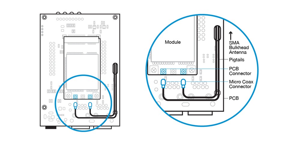
Why this works:
- The bulkhead connector (SMA bulkhead, N-type bulkhead, TNC bulkhead, etc.) is clamped to the enclosure.
- Antenna torque and user handling stop at the enclosure wall.
- The coaxial cable assembly isolates the PCB from strain, vibration, and repeated mating cycles.
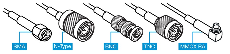
Choosing the right RF connectors (SMA, N-Type, BNC, TNC, SMP)
Connector choice is where most teams accidentally design-in future failures. Use connector families based on environment, mating cycles, and size.
SMA connectors (most common for compact products)
Use SMA when you need:
• a compact footprint
• wide antenna availability
• good performance at high frequencies
Watch-outs:
• SMA is easy to over-torque.
• If SMA is mounted directly to a PCB, it commonly cracks solder joints or lifts pads over time.
Best practice:
• Use an SMA bulkhead connector on the enclosure and a short internal coax jumper.
N type connectors (rugged, higher power, outdoor use)
Use N-type connectors when you need durability, sealing options, and lower loss at longer cable runs.
Best practice:
• N-type is almost always an enclosure/bulkhead interface, not a PCB interface.
BNC connectors (quick connect/disconnect, test setups)
BNC connectors are common in test or instrumentation environments. For products with frequent connect/disconnect, BNC may outperform threaded interfaces in service workflows, but it’s physically larger and not typical for small IoT enclosures.
TNC connectors (threaded BNC-style for vibration)
If vibration is expected and you like the BNC form factor, TNC connectors are often a better choice due to the threaded coupling.
MMCX / MCX (Compact Board-Level RF Connectors)
MMCX and MCX connectors are compact snap-on RF interfaces commonly used at the PCB edge to connect to an internal coaxial cable assembly. While they work well as a board-level transition point, they are not designed to absorb mechanical stress from external antennas. For enclosure-mounted antennas, a short pigtail should transition from MMCX or MCX to a bulkhead-mounted SMA or N-type connector to protect the PCB.
Selecting the coax pigtail: cable type, size, and durability
The “pigtail” isn’t just a cable; it’s a mechanical decoupler. Selection should prioritize bend life, strain relief, and repeatability.
Common choices:
• 1.13 mm micro-coax: ultra-compact routing, but easier to damage and kink
• RG-178: flexible, durable for many embedded devices
• RG-316: tougher jacket, better for harsher handling and higher-temp environments
Best practices:
• Keep the pigtail as short as routing allows (to reduce loss and clutter)
• Avoid tight radii and sharp bends (protect impedance consistency and bend life)
• Add strain relief near the PCB connector and near the bulkhead
• Route away from pinch points, screws, and enclosure seams
• For high-vibration or continuous shock environments, consider using locking micro-coax connectors such as I-PEX MHF 1 LK or MHF 4 LK, which provide improved retention compared to standard snap-on types
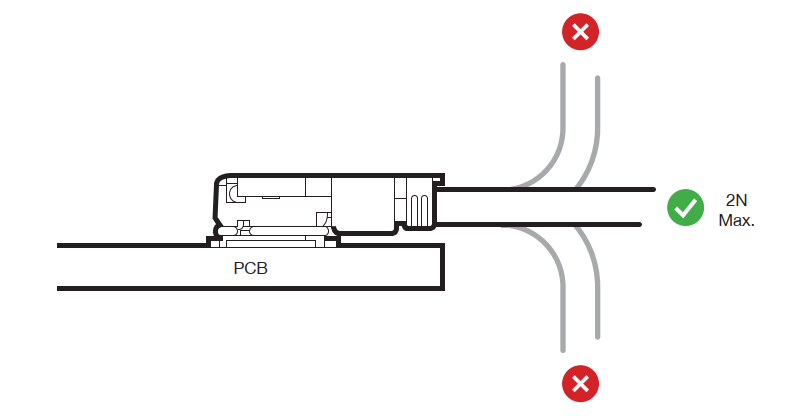
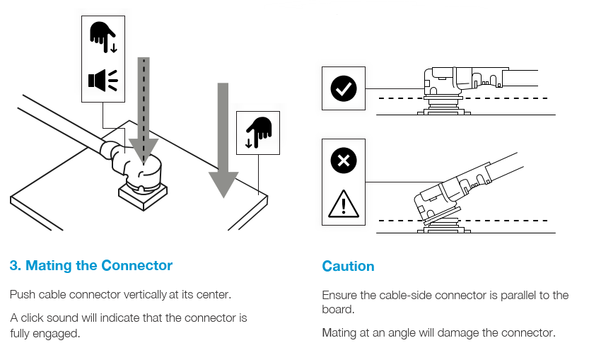
Image caption: At the mating connector, the cable should run flat along the PCB so that there is no leverage stress applied to the connector which could damage the connector and break the connection. If necessary, it is suggested that some hot melt glue be applied to the cable to attach it to the PCB to provide stress relief.
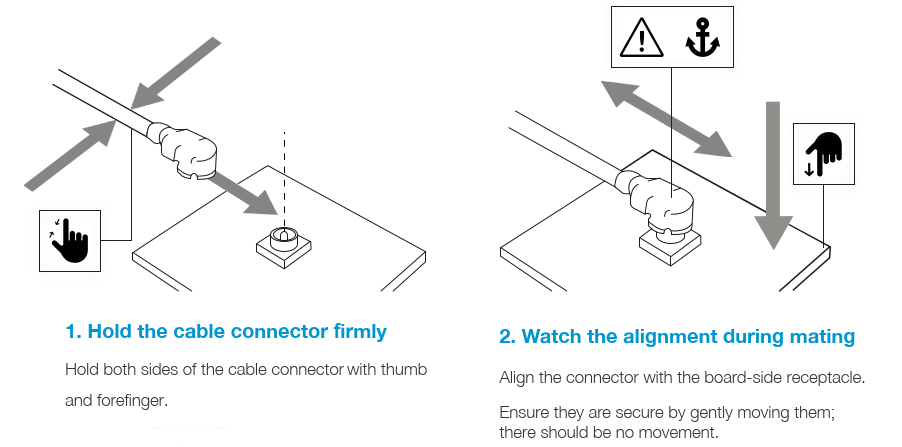
When mating micro-coax connectors such as U.FL, GSC, I-PEX MHF 1 or I-PEX MHF 4, correct installation technique is critical to avoid damage to the PCB receptacle. Always align vertically and press straight down onto the receptacle rather than applying side force.
Bulkhead connectors: the enclosure is your mechanical anchor
Bulkhead hardware is what makes the whole architecture reliable.
Best practices:
- Mount the bulkhead connector to the enclosure, not the PCB
- Ensure proper grounding on metal enclosures (good RF return path)
- Use lock washers and sealing rings as needed (especially for vibration or outdoor use)
- If the enclosure is plastic, consider grounding strategy and antenna placement carefully to maintain performance
The failure modes this design prevents (and how)
If your product is experiencing range dropouts, intermittent performance, or returns after installation, these are common culprits:
- PCB connector peel/lift from antenna torque
- Micro-coax damage from bending or assembly pinch points
- Intermittent contact from poorly supported coax transitions
- Ground/return discontinuity at the enclosure interface
A well-designed RF coaxial cable assembly stack-up eliminates most of these by keeping the mechanical load path in the enclosure.
When a custom RF cable assembly is worth it
Off-the-shelf pigtails are fine for prototypes, but production products often benefit from custom RF cable assemblies when you need:
- controlled length + routing
- specific connector combinations (U.FL or I-PEX to SMA bulkhead, MMCX to N-type, etc.)
- improved strain relief or ruggedization
- consistent performance across builds (repeatable loss/VSWR)
If you’re building at scale, “custom” often means fewer assembly defects and fewer field returns.
Takeaway
Antenna performance and RF interconnect design must work together. A high-quality antenna cannot compensate for a poorly designed RF cable assembly or mechanically unstable connector interface.
If you want fewer failures:
- anchor your connector at the enclosure
- use a short RF cable assembly inside
- protect the PCB from torque, bending, and vibration
For high-quality RF interconnect solutions, Siretta Ltd offers a comprehensive range of RF pigtail cable assemblies designed for industrial and IoT applications. Covering common connector configurations and frequencies from 150 MHz to 8 GHz, Siretta supports both standard and customised cable assemblies, allowing specification of connector types, cable lengths and shielding options to suit specific integration requirements.
Browse the full RF pigtail cable range here
