
Commonly adopted for high-speed WiFi and LTE, MIMO is a multiple input, multiple output antenna solution for wireless communications. MIMO is attributed to Arogyaswami Paulraj and Thomas Kailath through their proposed SDMA-based (Space-division multiple access) inverse multiplexing technique in 1993. Arogyaswami Paulraj went on to be awarded the Marconi Prize in 2014 for his ‘contribution to developing the theory and applications of MIMO antennas’.
The two common types of MIMO are SU-MIMO (single use) and MU-MIMO (multi use). SU-MIMO tends to have high latency if more than one user is accessing the network whereas, MU-MIMO has the capability to deal with multiple data streams running concurrently. Therefore, the modern day demands on data have made MU-MIMO the go to solution.
The MIMO methodology uses multiple antennas for both transmit and receive which provide higher speed, higher data links and enhanced connectivity. The MIMO approach minimizes errors as the data uses multiple signal paths concurrently without the need for extra bandwidth and power, making the solution ideal for harsher industrial environments. MIMO is also used for high-bandwidth communications requiring low interference.
MIMO systems provide higher data rates by employing Spatial Multiplexing techniques and higher reliability by applying the diversity techniques discussed below. The latest 3rd Generation Partnership Project (3GPP) added MIMO with Release 8 of the ‘Mobile Broadband Standard’ specifications for 4G and 5G allowing for 2, 4 or 8 sets of antennas within a MIMO communication interface. These can be used in different formats which can either multiply data pathways, increase speed, or improve signal strength.
Reliability and signal strength improvements are established by creating multiple versions of the same signal known commonly as Antenna Diversity, this generates multiple transmissions and enhances the chances of the signal being received whilst reducing fading. Fading is the fluctuation in signal strength received at the receiver and has a direct impact on the signal to noise ratio, which, in turn, adversely impacts error rate.
In LTE MIMO antennas are set up for Spatial Multiplexing, providing multiple transmit and receive channels. The data to be transmitted is split into streams which run concurrently. To avoid signal collisions the antennas are positioned spatially apart. There are 3 different methods for using this format:
• Spatial Multiplexing – multiple transmit / receive channels
• Spatial Diversity – multiple paired physically separated antennas
• Beam Forming – multiple directional antennas
Spatial Multiplex
Although several sets of antennas can be deployed in Spatial Multiplexing or Space-Division Multiplexing in many systems, it is often normal to see only two. The antennas at the transmitter and receiver are pairs which are mounted closely. It is important to note that fading can be an issue due to the electromagnetic fields generated from each antenna as their paths cross in the space between the devices. If the antennas are rotated a number of degrees from each other, their fields are less likely to cross and the risk of fading is reduced.
By reviewing the radiation field for each antenna, you should adjust their positioning through rotation to gain optimal performance. The best positioning will allow for optimal data transmission by multiplexing and sending balanced data loads which can double the transmission data rate across the transmitter.
MIMO Spatial Multiplexing requires that the number of receive antennas must be equal to or greater than the number of transmit antennas.
Spatial Diversity
Spatial Diversity is focused on signal integrity, usually using multiple antennas with similar characteristics that are separated, unlike spatial multiplexing where they are paired.
The method applied through spatial diversity reduces interference caused by multipath signals which is particularly useful in urban areas where fading is a major concern due to obstacles. By using multiple (up to 8) different channels and transmitting the same signal data with each antenna in a different polar field ensures any fading is negated when the receiver combines the signals and accepts the strongest point in each stream.
Beam Forming
Beam forming utilises multiple antennas in Spatial configuration but in this case all the antennas are faced directly at the target. Transmitting the same signal along a defined path can enhance the distance travelled. If the receiving antenna is also focused in a beam directed towards the transmitter considerable gain can be achieved.
Complex Antenna Solutions
The above methods cover many complex applications. LTE and 5G technologies now adopt the Beam Forming method in all base stations. WiFi has long adopted multipath connectivity in the latest versions of 802.11ac and 802.11ax which are specifically aimed at mobile clients, the base station or access points can utilise up to 6 MIMO antennas to form a broad coverage of the target area.
GPS by its nature of receiving signals from multiple satellites adopts a multiple antenna function to crossmatch the signals to produce the best fix both in position and time.
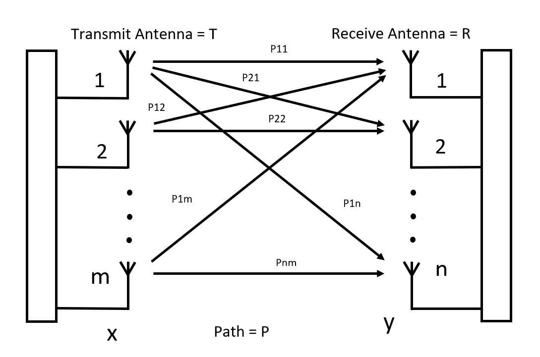 Here you can calculate the direct and indirect pathways, where the antenna for transmit is T1 to Tm, the Receiver antenna is R1 to Rn and the path is P. From this, a matrix can be built with a path dimension from P11 as the direct path and P21 the cross path.