
How to open Multiple Sockets Connection with Siretta Modems
Introduction
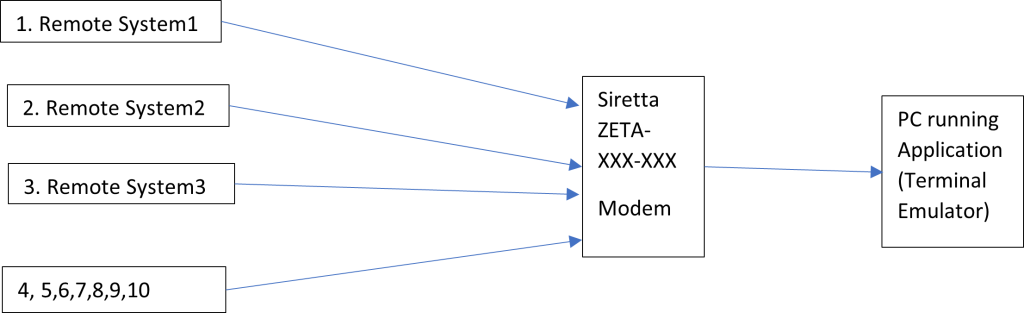
This application note explains how to simultaneously open up to 10 remote TCP/IP data sockets connecting to multiple destinations using Siretta’s advanced industrial modems. This feature allows users to monitor and connect to multiple end points and offers the ability to diagnose problems with remote equipment through the cellular network. All of the configuration is controlled using simple AT commands.
Remote System Connections
Resources used for this application note:
• Siretta Part Number: 61054 (ZETA-NLP-LTE1 (EU) Starter Kit (A Low Power Modem with RS232 and USB serial). Ultra Low Power LTE Cat 1 (EU) – Siretta – Enabling Industrial IoT
• Modem Starter Kit Quick Start Guide: ZETA-xxP Quick Start Guide
• Initial Modem Setup Guide Application Note: Initial Modem Setup Guide App Note – LP
• SIM card with the fixed public IP address
• A PC with an installed Terminal Emulator program (Window 10 Laptop installed with Tera Term used for the purpose of this guide)
• AT command reference manual for ZETA-NLP-LTE1 (EU)
Modem Set Up
1. Follow the Modem Starter Kit – Quick Start Guide.
2. Follow pages 1 to 5 of the Initial Modem Setup Guide Application Note.
3. Check the network registration state using AT+CREG?
NOTE:
//Receive following response when registered to a local network on 2G/3G:
+CREG: 0,1
//Receive following response when registered to a roaming network on 2G/3G:
+CREG: 0,5
//Receive following response when registered to a local network on LTE:
+CEREG: 0,1
//Receive following response when registered to a roaming network on LTE:
+CEREG: 0,5
Otherwise refer to ZETA-xxP Quick Start Guide or contact Siretta Support at [email protected]
4. Activate PDP context 1 using AT commands below: –
• AT+CGDCONT=1,”IP”,”APN Name”
• AT#SGACT=1,1,” APN Username”,” APN Password”
NOTE:
For this guide APN wlapn4.com, username and password OLANCHAG were used (which are specific to Siretta test SIM’s. APN parameters will vary depending on the mobile service provider that is used. See commonly used public APN details from the following link:fn
Common Global APN Settings for M2M Cellular Modems
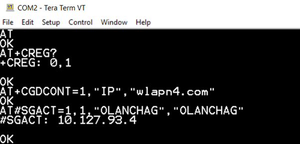
5. You will receive the response as seen in the screenshot above with an IP address as shown above when successful (Where 10.127.93.4 is assigned IP address for this guide):
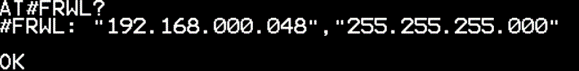
6. Check the Firewall settings using the following AT command AT#FRWL?
NOTE:
By default the firewall is enabled and to connect to the modem you must add an accept chain in to the firewall whitelist.
7. To add an accept chain in to the firewall, issue the following AT command
AT#FRWL=1,”X.X.X.X”,” Y.Y.Y.Y”
Where:
” X.X.X.X” is allowed IP address.
“Y.Y.Y.Y” is allowed subnet mask.
NOTE:
There are three available options for the firewall settings: 0,1 and 2
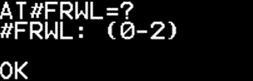
8.Issue the following AT command AT#FRWL=? to see supported values for your modem.
Where:
0 – Removes selected firewall index
1 – Adds accepted firewall entry
2 – Deletes all firewall entries
NOTE:
Default firewall settings will reject all incoming socket connections.
Only accepted firewall entries which have been added to the firewall whitelist are allowed to connect to the modem.
Entry shown below
Allowed IP address is set to “192.168.0.48” which means allow network address 192.168.0.48
Allowed subnet mask is set to “255.255.255.0” which means allow any IP in the 192.168.0 subnet
Firewall is enabled with a restricted IP addresses (Only incoming socket connections from 192.168.0.1 to 192.168.0.254 will be allowed to connect, all other IP connection attempts will be blocked)
![]()
In the above example to only allow the IP address 192.168.0.48 to connect to the modem then the firewall would need to be set to 255.255.255.255 to only allow the specific IP address host.
Disabling the firewall
For this guide the firewall was disabled using the following command:
AT#FRWL=1,“0.0.0.0”,”0.0.0.0”
Where:
Allowed IP address is set to “0.0.0.0” which means allow all IP addresses
Allowed subnet mask is set to “0.0.0.0” which means allow all subnets
NOTE:
With this entry added the firewall is disabled (Any incoming socket connection is allowed to connect).
Disabling the firewall is not recommended when integrating a Siretta Modem into your end application.
IMPORTANT – For security reasons the firewall MUST not be disabled using this command for production systems.
Opening Sockets
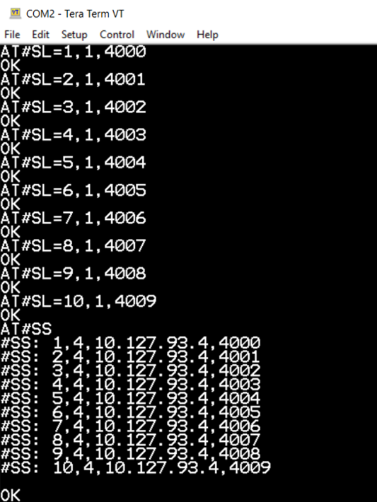
1. Open a listening socket 1 for TCP on Port 4000 using below AT command.
AT#SL=1,1,4000
2. Open a listening socket 2 for TCP on Port 4001 using below AT command.
AT#SL=2,1,4001
3. Open a listening socket 3 for TCP on Port 4002 using below AT command.
AT#SL=3,1,4002
4. Open a listening socket 4 for TCP on Port 4003 using below AT command.
AT#SL=4,1,4003
5. Open a listening socket 5 for TCP on Port 4004 using below AT command.
AT#SL=5,1,4004
6. Open a listening socket N for TCP/IP socket on Port 400(N-1) using the AT command below:
AT#SL=N,1,400(N-1) (N values are 1-10)
7. Check Socket status using the following AT command:
AT#SS
You will receive the response below indicating that all N sockets are active and waiting for incoming connections from remote devices.
NOTE:
For the status of the individual Sockets use the following at command:
AT#SS = Y
Where Y is the connection ID (1 to 10 used for the listening sockets in this guide)
Where:
Index 1 to 10 are the socket’s connection ID Available socket settings are below:
0 = Socket Closed
1 = Socket active / transferring data
2 = Socket suspended
3 = Socket suspended with pending data
4 = Socket listening
IP address 10.127.93.4 is the local (Private) IP address and 4000-4009 are the available local ports
Your local IP address will differ from connection to connection and in addition will differ depending on your ISP, APN parameters, network carrier and network technology.
NOTE:
Your local dynamic assigned IP address cannot be used for remote incoming data connections, you will need a SIM card with fixed public IP address for incoming connections. All public dynamic IP addresses block remote incoming data socket connections for improved security.
Checking socket configuration
Check socket configuration using the following AT command:
AT#SCFG?
You will receive response below for each socket
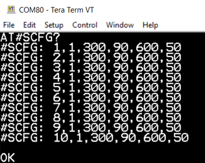
Where:
• 1-10 – Socket connection Identifier
• 1 – PDP context
• 300 (bytes) Packet size to be used for sending data when in online mode.
• 90 (seconds) socket inactivity timeout
• 600 (seconds) connection timeout
• 50 (milliseconds) data sending timeout
NOTE:
To see the range of supported values use the following AT command:
AT#SCFG=?
Shown below are the supported parameters for the available sockets.

Settings for opening multiple sockets from a Siretta industrial modem is now complete.
Testing Socket Connections
Socket Connection 1
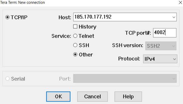
1. Use Tera Term on a local PC ‘Server PC’ which is connected to the internet and configure as shown below:
a. Use the fixed public IP address of the SIM card being used in the modem that you wish to talk to
b. Use port number 4000 to dial out to the listening Siretta modem to connect to listening socket 1
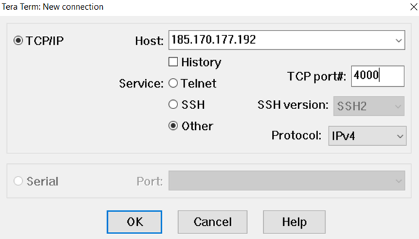
2. Click OK
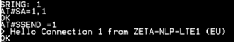
3. Observe the incoming socket connection request (SRING: 1) from the serial port of the Siretta modem connected to another PC running Tera Term which is connected to the modems serial port.
4. Accept the incoming data connection in command mode on the specified ID by issuing the following AT command:
AT#SA=1,1
5. Receive OK when a connection is successful.
6. Socket connection 1 is now established.
Socket Connection 2
1. Use Tera Term on a local PC ‘Server PC’ which is connected to the internet and configure as shown below:
a. Use the fixed public IP address of the SIM card being used in the modem that you wish to talk to
b. Use port number 4001 to dial out to the listening Siretta modem to connect to listening socket 2
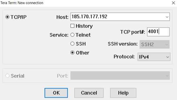
2. Click OK
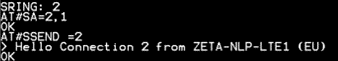
3. Observe the incoming socket connection request (SRING: 1) from the serial port of the Siretta modem connected to another PC running Tera Term which is connected to the modems serial port.
4. Accept the incoming data connection in command mode on the specified ID by issuing the following AT command:
AT#SA=2,1
5. Receive OK when a connection is successful.
6. Socket connection 2 is now established.
Socket Connection N
1. Use Tera Term on a local PC ‘Server PC’ which is connected to the internet and configure as shown below:
a. Use the fixed public IP address of the SIM card being used in the modem that you wish to talk to
b. Use port number 400(N-1) to dial out to the listening Siretta modem to connect to listening socket N
 #
#
2. Click OK
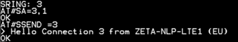
3. Observe the incoming socket connection request (SRING: N) from the serial port of the Siretta modem connected to another PC running Tera Term which is connected to the modems serial port.
4. Accept the incoming data connection in command mode on the specified ID by issuing the following AT command:
AT#SA=N,1
5. Receive OK when a connection is successful.
6. Socket connection N is now established.
Sending data to the connected Socket
1. Issue the following AT command from the Siretta modem’s serial port to send data to the remotely connected ‘Server PC’.
AT#SSEND = <ConnId>,<Bytetosend>
Where:
• ConnId = Socket connection ID (for this guide 1 to 10 are used).
• Bytetosend = size of the data to be sent in bytes
2. Once the command above is issued, the terminal will show “> “ where you can then enter / type data to be sent to the remotely connected ‘Server PC’.
3. To send click “Ctrl-Z”
4. You will receive OK on the local modem.
5. Data will appear on remotely connected ‘Server PC’.
6. You have successfully sent data to the remote equipment (See below).
NOTE:
A similar process is used to send data to the other socket connections, you only need to change ConnId as shown below.
For connection 2
For connection 3
Checking data from a connected socket
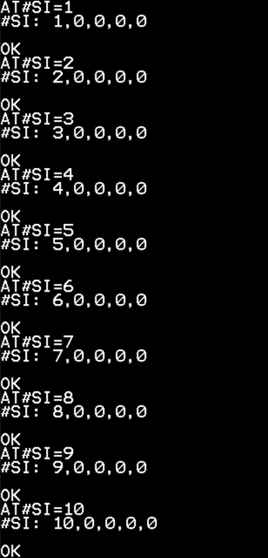
1. Issue the following AT command:
AT#SI=N
Where:
N = Connection ID (1 to 10 used for this guide) to check data on an individual socket
2. You will receive results in the following format
#SI: <N>,<Data sent in bytes>,<Data received in bytes>,<Total amount of data arrived in bytes>, <ack_waiting >,<Cause>
Where:
Cause = socket disconnection reason – available options are shown below:
0 = Socket not available
1 = Disconnection from remote application
2 = Connection close due to RST
3 = Socket inactivity timeout
4 = Network deactivation
3. For all data socket information issue the following AT command:
AT#SI
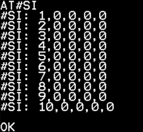
Where:
• N = ConnId 1 to 10
• Data Sent in bytes = 0
• Data received in bytes = 0
• Total amount of data arrived in bytes = 0
• Ack_waiting = 0
• Cause = 0
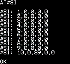
Example below shows socket ID 10 has 39 bytes of data arrive
Reading data from a connected socket
1. Issue the following AT command from the modem’s serial port to the read data from a connected socket
AT#SRECV = <ConnId>, <maxByte>[,<UDPInfo>]
Where:
• <ConnId> = Connection ID (1 to 10)
• <maxByte> = Maximum amount of data in bytes to read from socket
• UDPInfo = 0 or 1 (0 – UDP information is disabled, 1 – UDP information is enabled)
NOTE:
When UDPInfo is set to 1, the command will return the response as shown below:
#SRECV:<remoteIP>,<remotePort>,<connId>,<recData>,<dataLeft>
Where:
• <remoteIP> = The IP address of the sending host
• <remotePort> = The port used by the sending host
• <connId> = Connection ID (1 to 10)
• <recData> = Received data
• <dataLeft> = Remaining bytes in the datagram
NOTE:
If you issue AT#SRECV where there is no data present in the buffer, the command will return an ERROR.
2. To read 39 bytes of data from socket 10 issue the following AT command:
AT#SRECV =10,39
Example below shows 39 bytes of data have been read from socket ID 10

3. You have successfully read data from the remote socket.
For more information about Siretta Modem visit Industrial Modems – Siretta – Enabling Industrial IoT or contact your Siretta representative.
